
FWM 260÷909
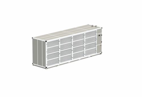
WATER-COOLED FAN WALL UNIT WITH PLUG-FAN EC INVERTER FANS


The new generation of water-cooled Fan Wall units includes a high-performance coil, high-efficiency filters, electrical panel, modulating valve, and Plug-Fan EC Inverter fans.
The units include the Modbus RTU communication protocol on an RS485 serial interface as standard. Other communication protocols and interfaces are available as options.
The units are designed to operate with high-temperature water and a wide delta T, in order to reduce energy consumption.
Versions
- FWMD - Fan Wall Draw Through
- FWMB - Fan Wall Blow Through
Power range
- 113-452 kW
- 32.0-129 Ton
Accessories
Factory fitted accessories
- CM Scheduler
- EC EC Inverter fans
- PA Differential pressure switch fans control
- PF Differential pressure switch filters control
- DPS Dual‑power transfer switch
- APS Automatic dual‑power transfer switch
- CAP Capacitive module for the microprocessor
- RTC Return air temperature control
- STC Supply air temperature control
- HS Humidity probe (read only)
- IW Inlet water temperature sensor
- OW Outlet water temperature sensor
- STT Remote air temperature sensors
- VVF Fans control: fixed speed
- VVP Fans control: proportional modulation
- VVE Fans control: ECO modulation
- AT Constant air flow regulation control
- AT/P Constant available static pressure regulation control
- IS Modbus RTU protocol, RS485 serial interface
- IST Modbus TCP/IP protocol, Ethernet port
- ISB1 BACnet MSTP protocol, RS485 serial interface, BTL certified
- ISBT BACnet IP protocol, Ethernet port
- ISBT1 BACnet IP protocol, Ethernet port, BTL certified
- ISS SNMP protocol, Ethernet port
- EM Energy meter
- EEM Energy efficiency meter
- MV 2 way modulating valve
- MVM 2-way pressure independent and balancing valve
- MVP 2-way pressure-independent valve with flow meter
- TIL Hydraulic connections top left
- TIR Hydraulic connections top right
- UIL Hydraulic connections bottom left
- UIR Hydraulic connections bottom right
- SIL Hydraulic connections left side
- SIR Hydraulic connections right side
- SA Water alarm sensor
- SB Fire sensor
- SC Smoke sensor
- RE Adjustable minimum/maximum voltage and phase control relay
- TY Coil with hydrophilic treatment
Loose accessories
- CR Remote control panel
- MP Condensate drain pump
Technical data
| 260 | 480 | 697 | 909 | |||
| Total cooling capacity (1) | kW | 113 | 226 | 339 | 452 | |
| Sensible cooling capacity - Max. (1) | kW | 113 | 226 | 339 | 452 | |
| Net sensible cooling capacity (1) | kW | 105 | 210 | 316 | 421 | |
| SHR (1) | % | 100% | 100% | 100% | 100% | |
| Water flow (1) | l/s | 2,71 | 5,41 | 8,12 | 10,83 | |
| Total pressure drops (1) | kPa | 153 | 153 | 102 | 133 | |
| Fan section | Fans | N° | 2 | 4 | 6 | 8 |
| Air flow (2) | m³/h | 26250 | 52500 | 78750 | 105300 | |
| Max. available static pressure | PA | 400 | 400 | 400 | 400 | |
| Absorbed power (2) | kW | 7,65 | 15,57 | 23,17 | 31,02 | |
| Filtration | Level according to EN779 | G4 | G4 | G4 | G4 | |
| Level according to ISO 16890 | ||||||
| Electrical characteristics | Power supply | V/Ph/Hz | 400/3/50 | 400/3/50 | 400/3/50 | 400/3/50 |
| Sound pressure | (3) | dB(A) | 67,3 | 70,4 | 72,2 | 73,4 |
| Cooling Module | Transport weight | kg | 0 | 0 | 0 | 0 |
| Operating weight | kg | 749 | 1275 | 1809 | 2321 | |
Dimensions
| 260 | 480 | 697 | 909 | |||
| Cooling Module | L | mm | 1904 | 3352 | 4804 | 6248 |
| W | mm | 1564 | 1564 | 1564 | 1564 | |
| H | mm | 2100 | 2100 | 2100 | 2100 | |
Notes
- 1 Temperatura aria ambiente 36°C - U.R. 30%, temperatura dell'acqua 20°C/30°C.
- 2 Portata d'aria calcolata con Prevalenza Utile di 400 Pa.
- 3 Pressione sonora rilevata a 1 m di distanza dall'unità, lato aspirazione.